These checks relate specifically to the design of column web doubler plates or transverse stiffeners for the column flange (also known as continuity plates). The primary reference for the design of these stiffeners is AISC Design Guide 13. However, the recommendations of this design guide are based on the LRFD 2nd edition design code. Therefore, many of the recommendations in DG-13 have been updated to reflect new or revised provisions in newer AISC 13th or 14th edition specifications. For this reason, RISAConnection will generally reference the relevant sections of the 13th or 14th edition codes rather than directly referencing DG-13.
The compression force that is required to be resisted by the transverse stiffeners is equal to the flange force transferred from the moment connection minus the capacity of the column flange or web to resist it. The highest demand force will be used based on the checks of flange bending, web yielding, web crippling, and web buckling.
Sections 4.3.2 and 4.3.3 of Design Guide 13 gives a minimum thickness for stiffeners based on section K1.9 of the LRFD 2nd edition. This has been updated to reflect the newer provisions of J10.8.
![]()
The transfer stiffeners are checked versus the demand forces. It is expected that the stiffeners will receive the force from the column flange and then be required to transmit that force as a shear force into the column web.
![]()
![]()
These checks are not discussed in Design Guide 13. However, AISC specification J10.8 and J4.4 have additional requirements for stiffeners that experience compression.
Note:
![]()
Refer to the Weld Calculations topic for more information about how weld strength and limitations are calculated for transverse stiffeners.
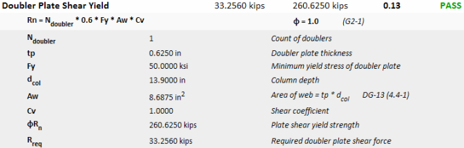
The shear force that is required to be resisted by the web doubler plate(s) is based on the excess shear force beyond the panel zone capacity itself.
Note:
To avoid encroachment of the column fillet, the minimum thickness of the doubler plate is determined from equation 4.4-4 of Design Guide 13.

Per recommendations of the AISC design guide 13 on column stiffening (see figure 4-3), the doubler plate will extend above and below the beam flange (or flange plate) a distance of 2.5k for directly welded connections and 3k+tp for end plate moment connections.
Note:
Equation 4.4-5 of Design Guide 13 refers to a minimum thickness to prevent shear buckling of the doubler plate. However, those code provisions have been updated since the release of the design guide. Therefore, RISAConnection uses instead the updated provisions of section G2-2(a).

Note:
Refer to the Weld Calculations topic for more information about how weld strength and limitations are calculated for doubler plates.